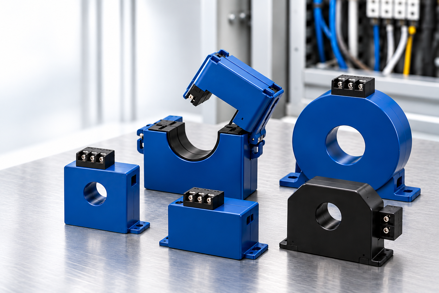
A current transformer (CT) steps a large AC current down to a small, proportional signal (typically 5 A, 1 A, or a low-voltage output) so meters, relays, and PLCs can measure the load safely without touching the conductor.
Think of a CT as a gearbox for current. A 600:5 CT is a 120:1 reduction: every 600 A flowing through the primary conductor turns into 5 A on the secondary, which your instrument can handle on a 14 AWG wire. Get the gearing right and you see every amp your motor, pump, or feeder draws. Get it wrong and you either read noise at light load or clip the signal at full load.
This guide is written for electrical and automation engineers who specify CTs for energy monitoring, motor protection, and PLC inputs. It covers the four decisions that cause the most field trouble: ratio, burden, core style, and safety. Each section answers the long-tail questions we hear most at CDI, and links to deeper articles when you need the next level of detail.
Table of contents
- Current Transformer Ratio
- Burden
- Split Core vs Solid Core
- Safety
- NK Technologies current and ground fault sensors from CDI
- Keep reading: current sensing articles
Current Transformer Ratio
The current transformer ratio is rated primary current divided by rated secondary current. A 200:5 CT outputs 5 A when 200 A flows through its window, so it has a multiplier of 40. Your meter reads the secondary and multiplies by 40 to show true load.
Iprimary = Isecondary × (Rated primary ÷ Rated secondary)
How to choose the right CT ratio
Size the CT to the circuit's maximum continuous current, not to inrush. A practical rule: pick the next standard ratio at or above 125% of full-load amps. Then check that normal running current sits between about 50% and 100% of the CT rating, where accuracy is best. A CT running at 5% of its rating is like weighing a letter on a truck scale: the reading is technically there, but it isn't useful.
| Load (full-load amps) | 125% target | Suggested ratio | Multiplier |
|---|---|---|---|
| 40 A pump motor | 50 A | 50:5 | 10 |
| 130 A air handler | 163 A | 200:5 | 40 |
| 320 A feeder | 400 A | 400:5 | 80 |
| 950 A main | 1,188 A | 1200:5 | 240 |
NK Technologies' solid-core 5 A secondary CTs cover standard ratios from 50:5 up to 1600:5, with the larger ratios reserved for the bigger aperture series.
What does 600:5 mean on a current transformer?
At 600 A primary, the secondary delivers 5 A. The multiplier is 120.
Can I use a 400:5 CT on a 100 A load?
Yes, but you only use a quarter of its range and lose resolution. A better fix is to loop the primary conductor through the window more than once.
How do primary turns change the ratio?
Each pass through the window adds one turn. Effective primary rating = rated primary ÷ number of passes. A 400:5 CT with four passes behaves like a 100:5 CT.
5 A, 1 A, or 333 mV secondary?
5 A is the legacy standard for panel meters and relays. 1 A cuts lead losses on long runs. 333 mV outputs connect directly to modern power meters and are safer to handle, covered in Safety.
Do I size for motor inrush?
No. Size for full-load current. A good metering CT tolerates short starting surges; protection relays that must measure fault current need a protection-class CT instead.
Burden
Burden is the total load connected to a CT's secondary, expressed in VA or ohms: the meter or relay input plus the wire running to it. If the burden exceeds the CT's rating, the core saturates and readings drift low, especially at high current.
Picture a pump pushing water through a hose. The CT is the pump, the secondary circuit is the hose. A longer, thinner hose means more resistance, and at some point the pump can't keep up. Long lead runs on small-gauge wire are the most common burden problem in the field.
Burden (VA) = Isecondary2 × Rtotal
Worked example: 5 A CT with a 50 ft run
- Lead length is 50 ft one way, so the loop is 100 ft.
- 14 AWG copper is about 2.5 Ω per 1,000 ft, so the leads add about 0.25 Ω.
- Lead burden = 5² × 0.25 = 6.3 VA.
- Add the meter input (often 0.1 to 0.5 VA). Total is roughly 6.5 VA.
A small 2.5 VA CT would be overloaded here. Choose a CT rated for at least the total burden, or reduce it: move the CT closer to the meter, step up to 12 or 10 AWG, or use a 1 A or 333 mV secondary.
Burden and accuracy class
IEEE C57.13 pairs each accuracy class with a standard burden. A CT rated 0.3 at B-0.2 holds ±0.3% ratio accuracy as long as the connected burden stays at or below 0.2 Ω (5 VA at 5 A).
| Standard burden | Impedance | VA at 5 A |
|---|---|---|
| B-0.1 | 0.1 Ω | 2.5 VA |
| B-0.2 | 0.2 Ω | 5 VA |
| B-0.5 | 0.5 Ω | 12.5 VA |
| B-0.9 | 0.9 Ω | 22.5 VA |
| B-1.8 | 1.8 Ω | 45 VA |
Why does my CT read low at full load?
Usually excess burden from long or undersized leads, or too many devices on one secondary.
Can two meters share one CT?
Yes, wired in series, as long as their combined burden plus leads stays under the CT rating.
Does polarity matter?
For amps alone, no. For kW, kWh, and power factor, yes: the H1 or dot side must face the source, and X1 must land on the meter's matching terminal.
Split Core vs Solid Core
Choose solid core for new builds where you can thread the conductor through before termination. Choose split core for retrofits where shutting down and disconnecting the circuit costs more than the CT.
A solid-core CT is a closed ring, like a key ring you must slide on before the key is attached. A split-core CT is a clamp that opens and snaps shut around a live, already-landed cable. The continuous ring gives solid core a small edge in accuracy and cost; the hinge gives split core its installation speed.
| Solid core | Split core | |
|---|---|---|
| Installation | Conductor must pass through before landing | Opens and clamps around an existing conductor |
| Downtime to install | Circuit disconnected | None in most retrofits (follow your site's live-work rules) |
| Accuracy | Highest; no air gap in the core | Slightly lower; the joint adds a small gap |
| Cost | Lower | Higher |
| Best fit | OEM panels, switchgear, new construction | Energy audits, retrofits, sub-metering, troubleshooting |
| Watch out for | Planning the conductor path early | Clean, fully latched mating faces; debris raises error |
Which NK Technologies CT fits?
- New panel, 5 A meter input: NK 5 A secondary CTs in round doughnut or foot-mount solid-core cases, with optional split-core versions.
- Big conductors or bus bar retrofit: The CT-MS split-core CT has a 2.22 in × 1.19 in window, ranges from 150 A to 800 A, and meets ANSI/IEEE C57.13.
- Sub-metering with modern power meters: ProteCT™ mV CTs are split-core as standard, with 0.85 in, 1.25 in, and 2.0 in openings and a 333 mV output.
- Straight to the PLC: AT Series current transducers combine a CT and signal conditioner, outputting 4–20 mA, 0–5 VDC, or 0–10 VDC in split- or solid-core cases.
Is a split-core CT accurate enough for revenue-grade metering?
Many are, but check the datasheet's accuracy class and burden. Solid core remains the safer default where billing-grade accuracy is mandatory.
Can I install a split-core CT on a live conductor?
The design allows it, but treat it as energized work. Follow NFPA 70E and your site's procedures.
Safety
The number one rule: never open the secondary of an energized 5 A or 1 A CT. A CT behaves like a current source. With no path for its current, it drives the secondary voltage as high as it takes, which can reach hundreds or thousands of volts, enough to injure an installer and destroy the CT's insulation. The secondary loop must always stay closed.
Practical safety rules
- Use shorting blocks. Short the secondary before removing a meter or relay, and open the short only after the device is reconnected.
- Ground the secondary at one point. Common practice is to ground X2 or the shorting block, so a primary-to-secondary insulation failure has a safe path.
- Check voltage ratings. The CT's insulation class must match the system voltage, such as 600 V class for low-voltage panels.
- Treat retrofits as energized work. Split-core installs on live conductors fall under NFPA 70E. Use proper PPE and procedures.
Safer by design
Two output styles remove the open-secondary hazard. ProteCT™ 333 mV CTs have a low-voltage secondary that NK states can be opened safely, so no shorting block is needed. Current transducers such as the AT Series condition the signal internally to 4–20 mA or 0–10 VDC, with the output magnetically isolated from the input.
Ground fault sensing: the CT's safety cousin
A ground fault sensor is a CT that watches for imbalance. All current-carrying conductors (phases and neutral, but not the ground wire) pass through one window. In a healthy circuit the currents cancel to zero. Any leftover current is leaking to ground, often through equipment, a person, or water. NK Technologies' ground fault relays trip on that imbalance, while their ground fault transducers report it as a signal so a PLC can trend insulation breakdown before it trips.
NK Technologies current and ground fault sensors from CDI
CDI distributes NK Technologies' full current sensing and ground fault line, so you can match ratio, burden, core style, and output in one conversation. Founded in 1982, NK Technologies builds current sensing, ground fault detection, and power monitoring products for industrial and factory automation, with more than 1,300 models designed and assembled in the USA.
| Need | NK Technologies product family |
|---|---|
| 5 A input to a meter, relay, or power transducer | 5 A secondary CTs, CT-MS split core |
| Safe, shorting-block-free sub-metering | ProteCT™ 333 mV CTs |
| A 4–20 mA or 0–10 VDC signal into a PLC | AT Series AC current transducers |
| Tripping on leakage to ground | Ground fault relays |
| Trending leakage before it becomes a fault | Ground fault transducers |
Not sure which ratio or output fits your application? Send CDI your full-load amps, conductor size, lead length, and meter or PLC input. We'll recommend the CT, check its burden, and quote it. Talk to a CDI current sensing specialist.
Keep reading: current sensing articles
This guide is the hub for CDI's current sensing content. Each article below goes deeper on one question and links back here.
| Article | What it answers | Links back to |
|---|---|---|
| How to Calculate a CT Ratio and Meter Multiplier | Multipliers, primary turns, nonstandard ratios | Current Transformer Ratio |
| CT Burden and Lead Length Calculator | Wire gauge, run length, VA budget | Burden |
| CT Polarity and Wiring for Power Meters | H1/X1 orientation, three-phase kW wiring | Burden |
| Split-Core CTs for Energy Retrofits | Sub-metering existing panels without shutdown | Split Core vs Solid Core |
| 5 A vs 333 mV vs 4–20 mA Outputs | Choosing an output for meters vs PLCs | Safety |
| Ground Fault Detection Explained | Zero-sequence sensing, relay vs transducer | Safety |
| Current Sensing Switches for Motor Status | Proving fans and pumps run, belt-loss detection | Split Core vs Solid Core |
Want the theory behind it? NK Technologies publishes a Current Transformers white paper and a Current Sensing Theory white paper.
Sources
- NK Technologies, 5 Amp Secondary Current Transformers: ratios 50:5 to 1600:5, case and aperture options
- NK Technologies, CT-MS announcement: window size, range, IEEE C57.13, company background
- NK Technologies, ProteCT™ mV CTs: 333 mV output, split-core case, openings
- NK Technologies, AT Series: outputs, case styles, isolation
- NK Technologies, Current Transformers white paper: CT theory
- NK Technologies, Current Sensing Theory white paper: current sensing background